


A magnetic loop antenna is a compact, efficient antenna that is ideal for portable operation or limited spaces and can be improvised inexpensively. A typical magnetic loop antenna looks like this:


Typically, magnetic loop antennas can be built from coaxial cable, hardline, solid copper, or aluminum tubing or ribbon. These magloops also have a very narrow bandwidth, necessitating the use of a variable capacitor for tuning to the operating frequency. As voltages on the order of thousands of volts develop across the capacitor, air variables or vacuum variable capacitors should be used. To maintain the lowest series circuit resistance, the connections should preferably be soldered, and a split-stator or “butterfly” capacitor is preferred.
Our topic here is not to show how to make a magnetic loop antenna, but to demonstrate how to make a high-voltage butterfly-style air capacitor, which is necessary for use with high-power transceivers.
In amateur radio groups, you have seen many discussions about these types of antennas and even low-power QRP devices with distances of thousands of kilometers. With enthusiasm like mine, you can find a few meters of aluminum or copper bars locally, bend them, and attach a variable capacitor similar to the one below, which can be found in old radios, and start using it.

However, those types of variable capacitors taken from radios generally perform well for listening, but when transmitting from the transceiver, they can withstand a power of 1 to 8 watts depending on their quality. Because the gap between the plates is very narrow, they will function if used with QRP radios. However, when the output power is increased, the voltage transmitted to the antenna rises, resulting in voltage spikes between the plates, which is undesirable.
Is there a solution for high wattage outputs? Of course there is. If your budget allows, vacuum type capacitors up to 15,000 volts can be purchased from online stores or eBay. Most of them are Russian-made and very successful. Some have high capacitance values ranging from 20 to 1000 pF and can support up to 20,000 volts. However, they are expensive. There are cheaper ones with lower capacitance values that cost around 150 to 200 USD.

If you don’t have the budget and want to make a cheap loop antenna, you can make a homemade air butterfly type capacitor. Let’s see what is required to build our own capacitor.
Required Parts:
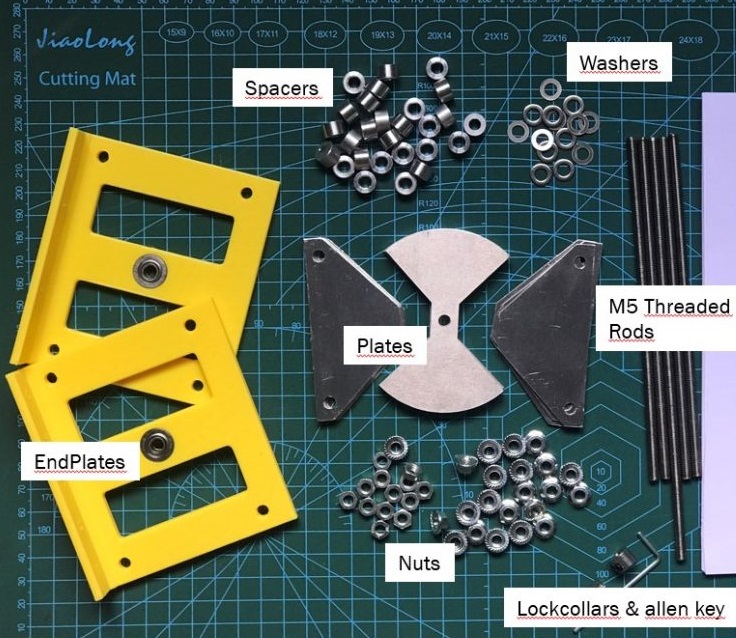
1- Rotor and stator plates, i.e. butterfly plates


If you want to buy laser-cut plates or complete DIY kits, you can get them from the following stores or send an email.
- TA2WK Etsy shop (Credit Cards)
- TA1LSX Ebay shop (Paypal, Credit Cards, Google Pay)
- Request with e-mail / erhan@ta2wk.com (You can get a more affordable price)
2- Threaded Rod (M5 type - 5mm)
The holes of the plates are set to 5 mm, so M5 metric threaded studs should be used.

Available from online and local hardware stores and DIY stores. If the capacitor will be exposed to the outdoor environment for an extended period, you can get a stainless steel one. Brass studs may be preferred, but they are more expensive than stainless steel. This is a matter of budget.
- TA2WK Etsy Shop https://www.etsy.com/listing/963834774/
- Amazon US https://amzn.to/3TN9dv0
- Amazon UK https://amzn.to/35xwOZc
- Aliexpress https://s.click.aliexpress.com/e/_ALDnX7
3- Spacer (or Nuts) for plate spacing
Aluminum Spacer, Unthreaded, M5 Screw Size , 5 mm ID
We will use it to provide a space between the plates. You will need five pieces for each set of plates. It is recommended that the space between the stator plates that we will lay against each other should be a 5 mm or 6 mm gap to avoid arcing at high voltage.
It is best to obtain regular-sized aluminum spacer parts (M5 type with a 5-5.1 mm bore and 5 mm or 6 mm wide).
Alternatively, you can use M5 nuts that are 4-6 mm wide (~1/4″). Additionally, 18-20 M5 nuts are required to attach the endplate panels. You can also use M5 flanged nuts for the endplates.
 or
or
Where to buy?
- TA2WK Etsy Store – 5 & 6 mm spacers https://www.etsy.com/listing/1011983171/
- TA2WK Ebay Store https://www.ebay.com/str/ta1lsxstore
4- M5 Nuts and Washers (or flanged nuts)
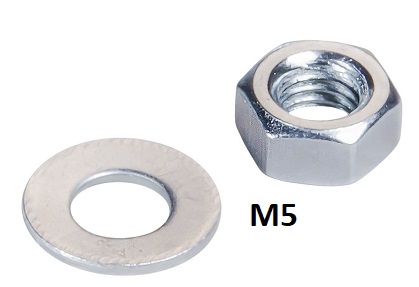
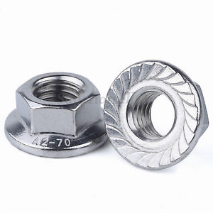
You will need 30–35 pieces of M5 size nuts and washers. I suggest getting some flanged nuts instead; they are all cheap and easy to find.
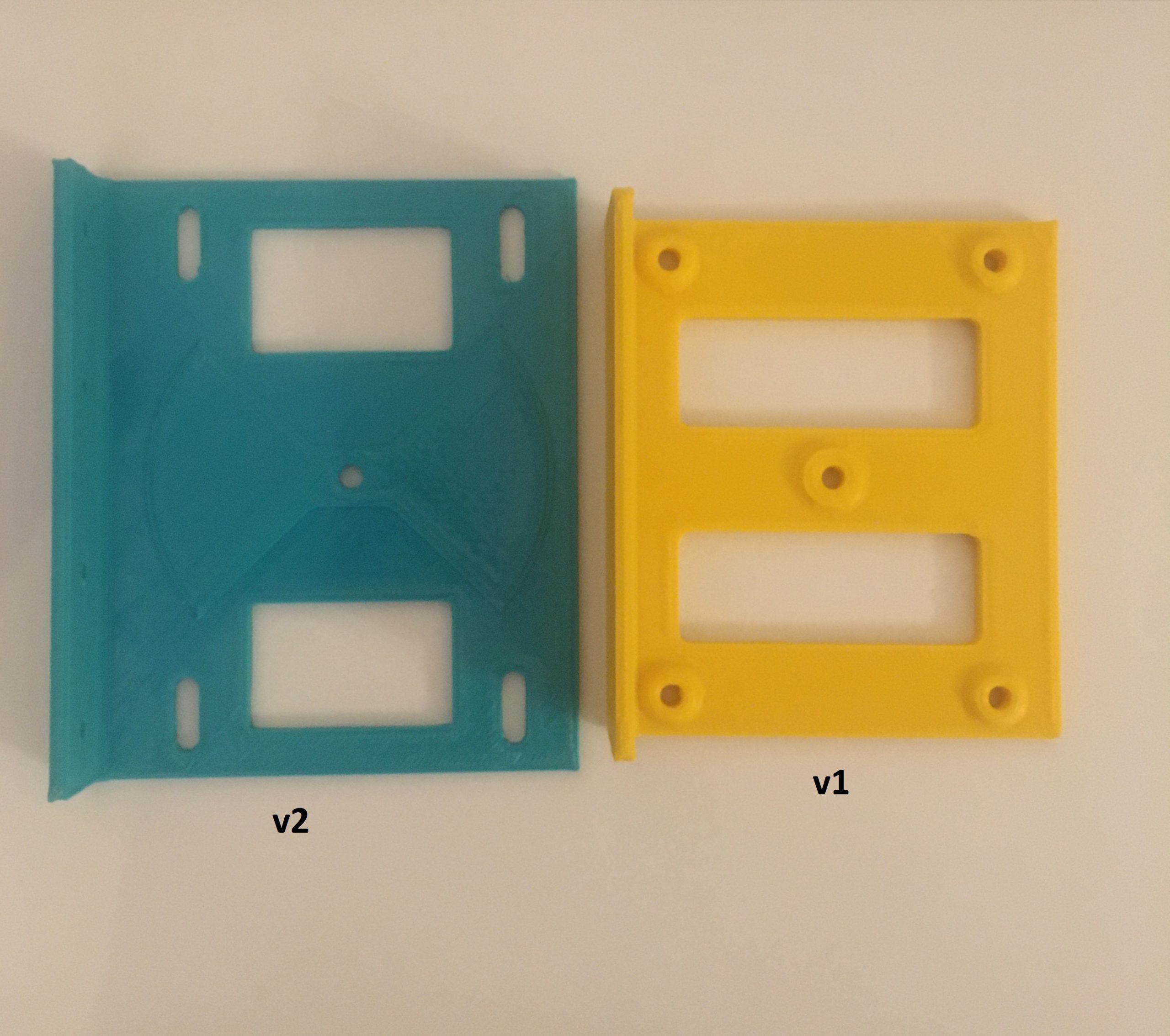
5- End Plates
When I made my first capacitor, I cut the acrylic plexiglass for the end plates, but it was a little difficult to match the stud holes. If you click on the picture below, my initial build video will open.

Then, I decided to build another one and designed an endplate in Fusion 360 that could be printed with a 3D printer. Afterward, I made a few more designs. I uploaded the STL files for free download from Thingiverse, Printables or Cults3d
If you don’t have a 3D printer around, you can buy 3D printed endplates from my Etsy Shop.


Optional - Openbuild Style Lockcollars - ID:5mm
It is recommended to apply a method of clamping and fixing the center rod from either side of the front end plate. This part does a good job if you don‘t have a planetary reduction drive or vernier dial knob. If you can‘t find this part, even though it is more troublesome, you can use an M5 nut and washer combination.

Where to buy?
- TA2WK Etsy Shop https://www.etsy.com/listing/982081841/
- Aliexpress http://s.click.aliexpress.com/e/_d7txP7y
Optional - Planetary Reduction Drives or Vernier Dial


Planetary reduction drive allows you to obtain finer tuning control with silky-smooth reduction, so that the driven bore rotates one time for every 6 rotations of the input knob. The ratio of 6:1 is good.
The Vernier Dial shown in the above picture is very similar to planetary reduction gears, but it allows only 180 degrees of movement, which is good for butterfly capacitors.
Where to buy?
- https://www.orenelliottproducts.com/product-category/planetary-reduction-drives/
- https://mgs4u.com/product/vernier-reduction-drive-14-inch-to-14-inch/
- https://www.ebay.com/itm/293729028212 (UK seller)
- https://www.ebay.com/itm/183091654116 (Vernier Dial)
- https://www.ebay.com/itm/175418526410 (Vernier Dial)
How many metal plate sets you will need?
It actually depends on the combination of your loop antenna specifications and the desired HF band. I suggest VK3CPU Magnetic Loop Calculator to determine the capacitance range.
- KI6GD capacitor calculator (exe windows application) http://www.alexloop.com/capcalc.exe
- https://www.66pacific.com/calculators/capacitor-calculator.aspx
| Capacitance pF | Suggested Max. | |||||
| PLATE SET (1mm thickness) | Spacer | Plate Spacing | min | max | Power | Voltage |
| 5 SET | 3mm/0.12″ | 1mm/0.04″ | 58 | 50 watt | 3,000 | |
| 4mm/0.16″ | 1.5mm/0.06″ | 39 | 100 watt | 4,300 | ||
| 5mm/0.20″ | 2mm/0.08″ | 29 | 200 watt | 5,900 | ||
| 6mm/0.24″ | 2.5mm/0.10″ | 1 | 23 | 200+ watt | 7,400 | |
| 10 SET | 3mm/0.12″ | 1mm/0.04″ | 131 | 50 watt | 3,000 | |
| 4mm/0.16″ | 1.5mm/0.06″ | 87 | 100 watt | 4,300 | ||
| 5mm/0.20″ | 2mm/0.08″ | 66 | 200 watt | 5,900 | ||
| 6mm/0.24″ | 2.5mm/0.10″ | 5 | 53 | 200+ watt | 7,400 | |
| 15 SET | 3mm/0.12″ | 1mm/0.04″ | 204 | 50 watt | 3,000 | |
| 4mm/0.16″ | 1.5mm/0.06″ | 136 | 100 watt | 4,300 | ||
| 5mm/0.20″ | 2mm/0.08″ | 102 | 200 watt | 5,900 | ||
| 6mm/0.24″ | 2.5mm/0.10″ | 9 | 79 | 200+ watt | 7,400 | |
| 20 SET | 3mm/0.12″ | 1mm/0.04″ | 277 | 50 watt | 3,000 | |
| 4mm/0.16″ | 1.5mm/0.06″ | 185 | 100 watt | 4,300 | ||
| 5mm/0.20″ | 2mm/0.08″ | 139 | 200 watt | 5,900 | ||
| 6mm/0.24″ | 2.5mm/0.10″ | 12 | 110 | 200+ watt | 7,400 | |
| 25 SET | 3mm/0.12″ | 1mm/0.04″ | 350 | 50 watt | 3,000 | |
| 4mm/0.16″ | 1.5mm/0.06″ | 233 | 100 watt | 4,300 | ||
| 5mm/0.20″ | 2mm/0.08″ | 175 | 200 watt | 5,900 | ||
| 6mm/0.24″ | 2.5mm/0.10″ | 15 | 136 | 200+ watt | 7,400 | |
| 30 SET | 3mm/0.12″ | 1mm/0.04″ | 423 | 50 watt | 3,000 | |
| 4mm/0.16″ | 1.5mm/0.06″ | 282 | 100 watt | 4,300 | ||
| 5mm/0.20″ | 2mm/0.08″ | 212 | 200 watt | 5,900 | ||
| 6mm/0.24″ | 2.5mm/0.10″ | 19 | 163 | 200+ watt | 7,400 | |
For QRP operations, you can use a butterfly capacitor in parallel wiring mode to get four times the capacitance. (Short both stators and wire the rotor and stator.)
How to assembly?
Step 1- Cut four pieces of M5 threaded rod for the stators. For the twenty set plates, 15 cm is enough; however, cut the middle rod a little longer, around 4–5 cm, as you will need to insert a knob to turn it or attach a motor.
Step 2-Take two stator rods and insert flanged nuts (or a regular nut and washer) leaving a 2 cm gap from the end of the rod.
Place the stator plates and spacers as shown in the picture below (using half of the stator sets), and secure them with the flanged nuts on top. Finally, tighten the nuts on both sides with pliers.
Repeat the same for the other side of the stator plates, the center rod, and the rotors.


Step 3- Take one of the end plates and insert the stator rods, positioning the lower mounting part outside as seen in the picture below. To fix the stator rods with the end plate, use washers and nuts together, or you can use flanged nuts; it doesn’t matter.

Step 4- Insert a regular M5 nut next to the flanged nut on the center bar. See the following picture.
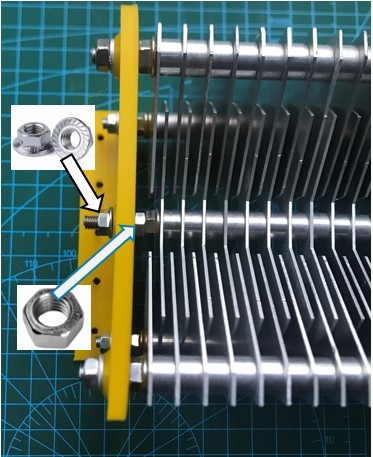
Then carefully insert the center rod into the center hole of the endplate and insert a flanged nut, but keep it loose. The rotor and stator plates should align with that position, but we will fine–tune that while assembling the other side.
For the other side; Insert nuts+washers to the stator rods and align them. Insert a lock collar to the center rod and keep it loose for now.

Step 5- Place the other endplate.
Insert nut+washer to the stator rods and tighten all of them from both sides.

Insert another lock collar onto the center rod and you can move the center rod back and forth slightly to align the rotor plates with the stators. Then lock the lock collars from both sides using the Allen key (see the red circle below).

This is the result. 🙂

Examples


YouTube videos of ham radio operators making beautiful capacitors using TA2WK butterfly capacitor plates or kits
- M0MSN Magnetic Loop Capacitor Build https://youtu.be/dXrfOVt8xzU
- M0MSN Mike’s Youtube Channel – The “Capacitor” (Mike shares a lot of cool projects as well as nice loop antennas, I suggest you follow him)
Magnetic Loop Controllers and Motor Controller Systems
- Greg KF5N Magnetic Loop Controller Project (Fork from J.Pardum’s version) v2
- Jack Purdum‘s Magnetic Loop Controller Project https://groups.io/g/SoftwareControlledHamRadio
- Dave‘s (G7IYK) MagLoop Tuner Project https://www.instructables.com/Magnetic-Loop-Antenna-Automated-Tuner/
- EA7HVO‘s Magnetic Loop Controller (for 4 Antennas) https://www.instructables.com/Magnetic-Loop-Controller-for-4-Antennas/
- Loftur‘s (TF3LJ / VE2LJX) Automatically tune a Magnetic Loop Antenna Project
- Cheap Stepper Motor Driver Controller (Aliexpress)
-
ZK-SMC01 Stepper Motor Controller (Aliexpress, Amazon)
- WiFi Controllers
Some suggested magloop related sites;
- https://www.nonstopsystems.com/radio/frank_radio_antenna_magloop.htm
- https://ki5aif.wordpress.com/2019/07/26/capacitor-selection-and-design-for-magloop-antennas/
- https://k1fm.us/2014/06/k1fm-mini-magnetic-loop/
- https://www.qsl.net/kp4md/magloophf.htm
Magloop & Capacitance Calculators
- VK3CPU Magnetic Loop Calculator
- 66pacific Capacitance Calculator
- 66pacific Small Transmitting Loop Antenna Calculator
- Alexloop Capacitor Calculator
73, TA2WK

![]()
To keep this blog up and running you may also use following affiliate links to buy your needs from there. Cheers...
![]()
![]()
This page contains some affliated product links. #affiliate #reklam


